 |
|
|||||||||
| Home | History | Support | Articles | Screenshots | Download | F.A.Q. | Beta Area | Advertise here |
|
SpeedFan 4.52 Copyright 2000-2020 by Alfredo Milani Comparetti |
What is PWM and what is the difference between Analog and Digital?
PWM is for Pulse Width Modulation. Let us introduce a few elements. First of all we need to know
the difference between an Analog signal and a Digital one. Let's think about a 9V battery, one of
those batteries that we use in our remote controls for our stereo and tv. A 9V battery produces
an analog signal whose voltage is about 9V. We may expect its voltage to be somewhere near 9V,
but not exactly that value. If we would like to guess which is the actual voltage we should guess
out of an infinite number of values, as any value from, say, 0V to 10V is possible. An analog
signal is something with these features. A digital signal, on the other hand, is something that
can assume a finite range of values. {0 or 1}, {0V or 5V}, {1, 2, 3 or 4} are examples of which
values a digital signal can assume at any time. The disadvantage of analog circuits is that they
tend to drift with time and they are difficult to tune. Analog circuits are usually hot and are
sensible to noise. If we look at an analog signal, we can expect any real number from it and we
can't identify for sure what's noise and what's signal. If we look at a digital signal that
can assume a value of either 0V or 5V, even a reading of 4V can be identified as a reading error
and we know the real value was actually 5V. A digital signal is, therefore, easier to implement,
requires a smaller circuit, can be fine tuned, is easily reproducible, dissipates less heat, is
immune to noise and weights less.
What is modulation?
 Now that we know the difference between an analog and a digital signal, we need to figure out
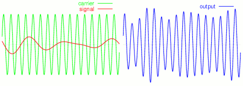
what modulation is. We all know about AM and FM in radios. Let's have a quick look at AM. AM is
for Amplitude Modulation. It is a way to send a signal (our music) over a carrier (the frequency
of our favourite radio station). Modulation is basically a way to encode one signal on a carrier
signal.
Back to the point
 Now that we know a little bit more about analog and digital signals and about modulation, we can
get back to the point: what is PWM and why is it useful for our fans? A pulse width modulated
signal is a way to simulate an analog signal by means of a digital one. Let's assume we need to
apply a variable voltage to a device (like a lamp). We need to apply a voltage ranging from 0V
to 5V and we need to do it having only two available outputs: 0V and 5V. We will identify our
PWM by two parameters: the clock cycle and the duty cycle. All we need is a clock and a counter.
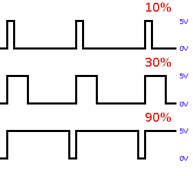
In the image we can see the output from our PWM when our duty cycle is either 10%, 30% or 90%.
When we are outputting a 10% duty cycle, we are sending 5V to our load (the lamp) for 10% of the
whole period and 0V for the remaining 90% of the period. This means that, over the full period,
the average voltage is 0.5V. With a 30% duty cycle, we are sending 5V for 30% of the period and
0V for the remaining 70%, thus simulating 1.5V. With a 90% duty cycle, we are sending 5V for 90%
of the period and 0V for the remaining 10%, thus simulating 4.5V. But the duty cycle is not the
only thing we can act on. The frequency with which this alternancy occurs is very important.
Let's think about our lamp. Let's assume we send 5V for 10 seconds and 0V for 90 seconds. We'll
see our lamp shining brightly for 10 seconds and then completely off for 90 seconds. This is not
what we planned to achieve and it means that we need to use the right frequency when applying
those two different voltages. The right frequency depends on the characteristics of the load.
Basically it depends on how fast the load reacts to changes. We can experience the same problem
if we use too high a frequency. If the frequency is too high, the lamp might not be able to
reproduce the full range of available (simulated) voltages and might end up appearing either
completely on or completely off.
How can we apply PWM to the fans inside our PC?
How can we apply PWM to the fans inside our computer? PWMs are used for several tasks, but we
are focusing on their usage related to fan speed control. Every fan uses a DC motor. DC is for
Direct Current (or Continuous Current), distinguishing it from AC, which is for Alternating
Current. Applying a nominal voltage to a DC motor we can make it run. DC motors can work even
with voltages lower than the nominal one. When a lower voltage is applied, the motor runs more
slowly. By using PWM we can feed the DC motor with different voltages, based on a duty cycle and
on a PWM clock frequency. We must remember that a DC motor needs some current to run. Our digital
device can output, say, either 0V or 5V, but with a low current. In order to drive a real fan,
some additional circuitry is needed. This circuitry will, most likely, change the 5V output into
a 12V output and will be able to send more current to the DC motor. This is the reason why some
motherboards, even if they do have some chip which is able to generate a PWM output, are still
unable to control fan speeds: because this additional circuitry is missing.
What is the influence of PWM on fans' reported RPMs?
 Fans that do use 3-wire connectors can report their speed. RPM is for Revolutions Per Minute.
This result is achieved by using two plates. One is located on the fixed part of the fan (the
frame) and one is located on the moving part of the fan (the blades). One plate is connected to
the power source and the other one is connected to the wire that goes from the fan to the hardware
monitor chip. Whenever the first plate faces the second one, some current flows through the
latter and our sensor can detect it. By counting how many times, in a finite amount of time,
the two plates face each other, our sensor can determine the RPMs. The problem related to PWM driving the
fan is that when the two plates face each other there might actually be no current flowing at
all. We should remember, in fact, that PWM alternates full power with 0V. Depending on the
frequency used by our PWM generator and on the characteristics of the fan itself, we might
get odd results.
|
You can rate this article.
|
By Alfredo Milani Comparetti (alfredo [at] almico.com)
|
| Page generated in 0.08 seconds | Powered by (new)... | Page viewed 607272 times |
| - | Did you know that SpeedFan has an |
Privacy policy |